Home
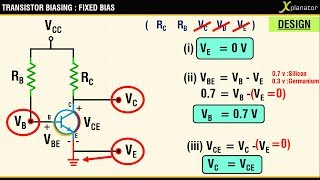
FIXED BIAS CONFIGURATION FOR A BJT | ANALYSIS AND DESIGN
6 years ago
7:37
NOR GATE AS UNIVERSAL LOGIC GATE : PART 3| XOR, XNOR
6 years ago
7:17
NOR GATE AS UNIVERSAL LOGIC GATE : AND,NAND|PART2
6 years ago
4:46
NOR GATE AS UNIVERSAL LOGIC GATE | NOT,OR | PART 1
6 years ago
5:31
Impromptu Speaking : Farewell Speech for a mentor
6 years ago
5:39
Impedance Transfer in a Transformer
6 years ago
8:54
PHASOR DIAGRAM ( INDUCTIVE LOAD) FOR A SINGLE PHASE TRANSFORMER
6 years ago
11:38
SINGLE PHASE TRANSFORMER : EQUIVALENT CIRCUIT AND WORKING
6 years ago
8:39
SERIES RC and AC supply : CURRENT | POWER | PHASOR DIAGRAM
6 years ago
7:43
SERIES RL and AC supply : CURRENT | POWER | PHASOR DIAGRAM
6 years ago
7:29
PURE CAPCITOR ACROSS AC SUPPLY: CURRENT EQUATION|POWER EQUATION|PHASOR DIAGRAM|POWER PLOT
6 years ago
7:12
RMS value of Voltage/Current : The basics using concept of areas
7 years ago
5:19
Average Value of Voltage/Current wave :The basics using concept of areas
7 years ago
4:32
Pure Inductor and AC:Voltage|Current|Power|Phasor Diagram|Waveforms
7 years ago
7:58
Resistance on AC Supply: Voltage|Current|Power Equations|Phasor Diagram|Graphs
7 years ago
5:56
Waveforms for Class C/Complementary Thyristor [SCR] commutation circuit
7 years ago
7:10
Waveforms/Graphs for Class D Thyristor/SCR commutation
7 years ago
5:42
Class D / Auxillary /parallel capacitor commutation for a thyristor(SCR)
7 years ago
5:33
Class C /Complemenatry commutation for Thyristor(SCR)
7 years ago
4:36
[Waveforms/Graphs] Class B commutation circuit for thyristor(SCR)
7 years ago
6:00
Class B/Resonant Pulse commutation for Thyristor(SCR)
7 years ago
6:12
Three Phase Inverter - 120 degree operation with Voltage Graphs
7 years ago
8:21
Three Phase Inverter under 180 degree operation and the asscociated waveforms
7 years ago
7:27
Working of Inductor and Capacitor LC circuit with a DC supply, a graphical study
7 years ago
2:18
SCR Phase Controlled Rectifier_RL Load witha guide to plotting graphs
7 years ago
4:41
Thyristor RC Firing Circuit Half Wave with step by step analysis of graphs
7 years ago
2:50
RC Firing Circuit for Thyristor (SCR) full wave and graphs
7 years ago
3:02


![Waveforms for Class C/Complementary Thyristor [SCR] commutation circuit](https://i.ytimg.com/vi/cNLECyRbww8/mqdefault.jpg)


![[Waveforms/Graphs] Class B commutation circuit for thyristor(SCR)](https://i.ytimg.com/vi/U5_pHR6e0t0/mqdefault.jpg)


